Creating an FK-IK switch arm in Maya with the Node Editor is not too complicated approach you can implement for your next character rigging project.
In this article, we will demonstrate the FK-IK switch setup for the arm of our character. But make no mistake, the same principle can be applied for other parts of a character, such as leg, and torso.
The theory behind FK-IK switch in Maya is to create a controller that determines which set of controls (FK or IK) will be used to drive the movement of the character. However in order to take advantage of this rig setup, we have to previously create those separate setups (FK and IK rigs) for our character.
If you need more information, keep reading..
How to create the individual FK and IK rig setup (Overview):
So before we implement the FK-IK switch through the Node Editor in Maya, we need to create those individual setups for both FK and IK rig of the arm. That includes joints, curve controllers, and constraints.
Even though the creation of the separate (FK and IK) setup is not in the scope of this article, here is a few notes on how to approach it.
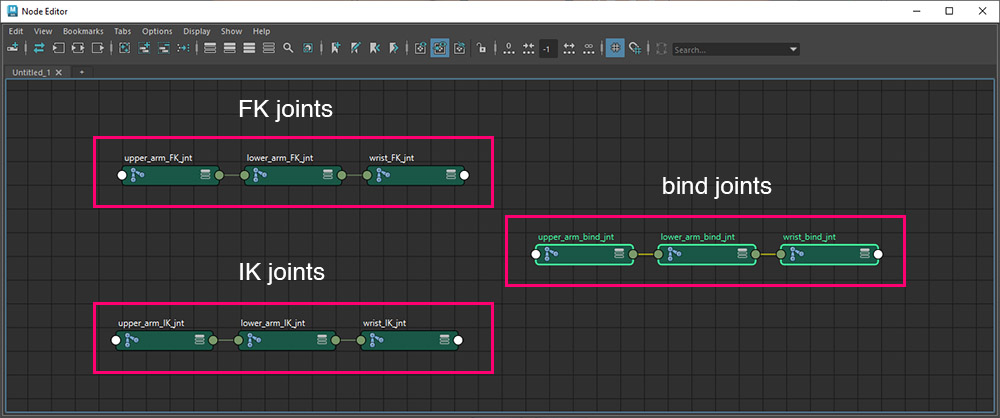
- create three joint chains (bind, FK, and IK joints)
- create curve shapes for controllers
- and lastly all the necessary constraints
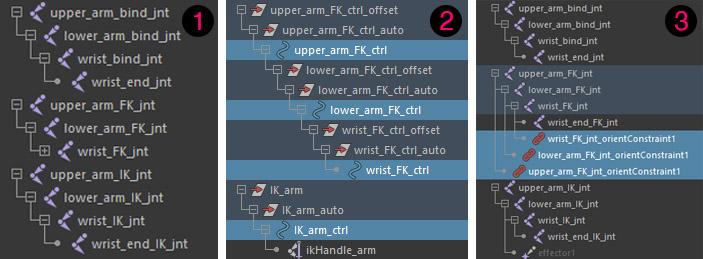
Note: The process is to create the bind joints, and then duplicate the whole parent node two times. One for the FK joints and one for the IK joints. After that, rename both chains accordingly.
Note: Then bind joints, will be used for bind the mesh and as a result will drive the final motion of our character.
You can easily create the rig for the FK setup using this python script.
For the IK rig setup, you just need to create an IK handle and then parent that IK handle under a curve shape for a cleaner controller.
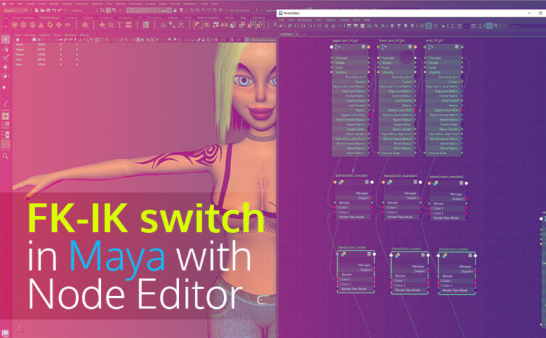
Prepare the nodes in the Node Editor:
Assuming you already have the FK and IK rig setup, let’s see how we will create all the necessary connections in the Node Editor in Maya.
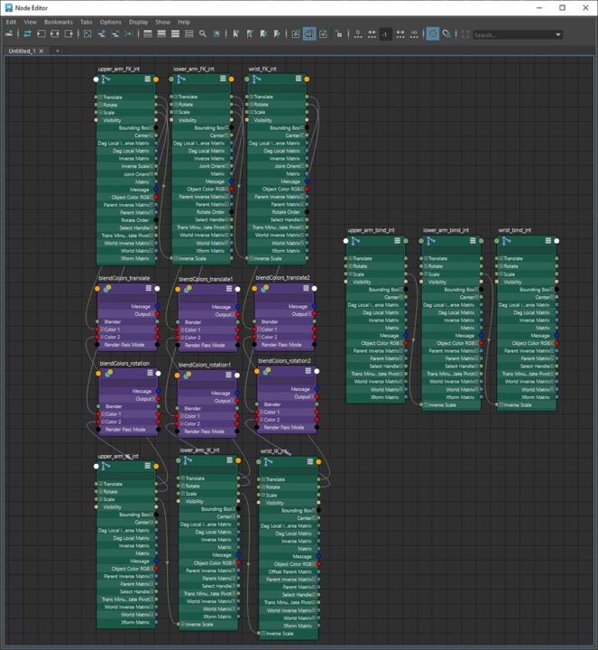
Select one by one all the necessary joints from each rig setup (bind, FK, IK) and drag and drop them into the Node Editor. We have three joints for our arm (upper_arm, lower_arm, wrist).
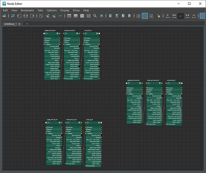
Select all those joints in the Node Editor and click on the “show primary attributes on selected nodes” icon.
This will expand all the options for those nodes.
Make the blend connections in the Node Editor:
We need to create three new nodes twice. One time for the translate and one for the rotation parament.
Blendcolor nodes for translate:
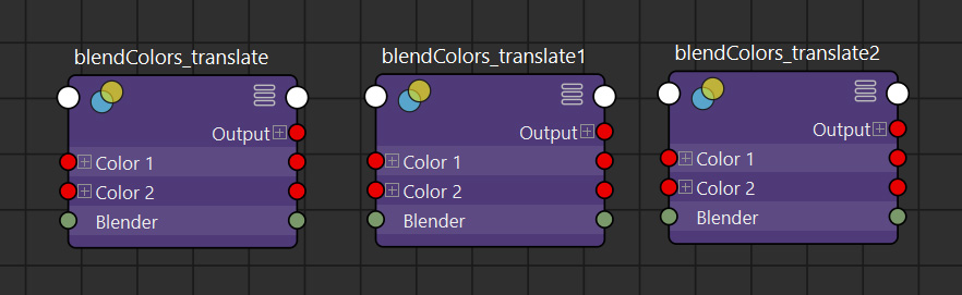
Create three blendcolors nodes, by pressing “Tab” and write “blendcolors”. We need three blendcolors nodes because our arm rig consists of three joints (upper, lower, and wrist).
After you create those blendcolors nodes, expand them, with the same icon previously (show primary attributes on selected nodes). Feel free to rename those paraments, for organization purposes.
Make connections:
Now we need to make some connections. Let’s make the FK connections first.
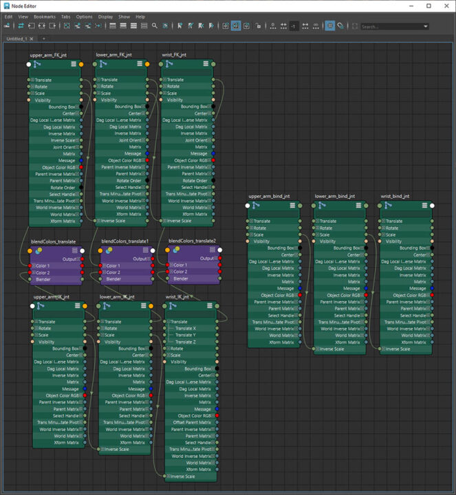
Connect the translate parament from the upper_arm_FK_jnt to the color 1 from the blendcolors node. The translate parament from the lower_arm_FK_jnt to the color 1 from the second blendcolors node. And the translate parament from the wrist_FK_jnt to the color 1 from the third blendcolors node.
Let’s make the IK connections as well.
Connect the translate parament from the upper_arm_IK_jnt to the color 2 from the blendcolors node. The translate parament from the lower_arm_IK_jnt to the color 2 from the second blendcolors node. And the translate parament from the wrist_IK_jnt to the color 2 from the third blendcolors node.
Blendcolor nodes for rotation:
Create another three blendcolors nodes this time for rotation parament. Expand them and create the connections as previously. Only this time make the connection between rotation and color 1 and 2, and not translate.
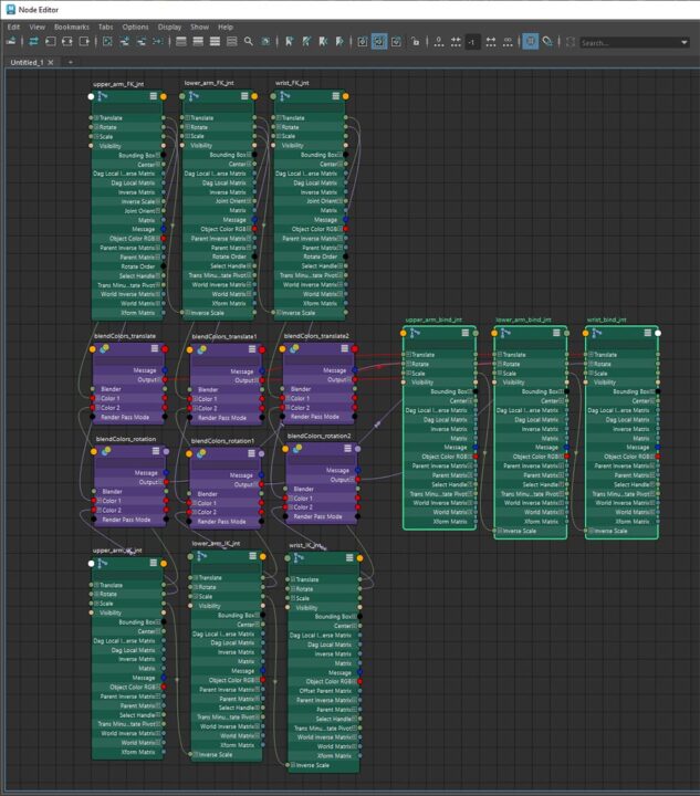
Blendcolor nodes connection to the bind joints:
Lastly, connect all six blendcolors nodes (translate and rotation) with the bind joints.
Translate blendcolor nodes:
- Connect the output from the blendcolor to the translate parament of upper_arm_bind_jnt
- Connect the output from the blendcolor 1 to the translate parament of the lower_arm_bind_jnt
- Connect the output from the blendcolor 2 to the translate parament of the wrist_bind_jnt
Rotation blendcolor nodes:
Connect the output from the blendcolor to the upper_arm_bind_jnt
- Connect the output from the blendcolor to the rotate parament of the upper_arm_bind_jnt
- Connect the output from the blendcolor 1 to the rotate parament of the lower_arm_bind_jnt
- Connect the output from the blendcolor 2 to the rotate parament of the wrist_bind_jnt
How to use FK-IK switch:
If we try to move a controller either FK or from IK, we will realize that the controller has a half-effect. The reason for that is because every blendcolors node we create, by default, has a value of 0.5 on the blend parament (minimum=0 and maximum 1). So the result would be that both FK and IK controllers will have half effect, no matter what controller we moved.
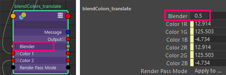
So in order to switch between FK-IK controllers for our arm, we need to change the blender node for all six blendcolor nodes we created (3 x translate, 3 x rotation). Change the value to 1 for FK controls, and to 0 for IK controls.
We can do that manually through the Node Editor every time we want to switch between two systems (FK -IK), by selecting one by one the six blendcolors nodes and changing the blender parament through the Channel Box. But as you can imagine this is not the most efficient way to do that.
Instead, we will create a circle curve shape controller and add a custom attribute on it (FK-IK switch). We will connect that custom attribute with all six blendcolors nodes for the blender parament. So when we want to switch between FK and IK rig systems, we will do that through only one attribute (FK-IK switch).
Create the FK-IK switch controller arm in Maya:
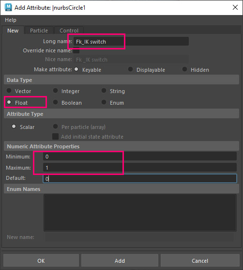
We want to create a nurbes circle shape to carry the custom attribute (FK-IK switch).
Go to Create – Nurbs Primitives – Circle. Feel free to reposition it wherever it suits you.
Select it and open the Channel Box. Go to Edit – Add Attribute. Give a described name for the new attribute, set it to float, and lastly, set 0 value for minimum and 1 value for maximum.
Make the connection in the Node Editor:
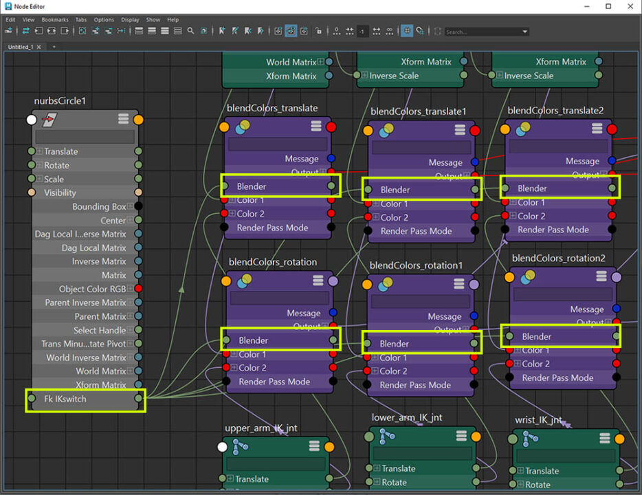
Now we have our new controller with the custom attribute, the final thing we want, is to make the connection between this custom attribute and all six blendcolors nodes (blender parament).
Select the nurvsCircle shape you created and added to the Node Editor. Expand it and connect the FK IK switch parament to the Blender parament from all six blendcolors nodes.
That was it.
Every time you want to use the FK controllers, you can select the nurbs circle you created and set the FK IK switch attribute to 1 through the Channel Box. If you want to use the IK controller, set the same attribute to 0.
Note: We can also connect the fk-ik switch with all six blendcolors nodes with a set-driven key method.